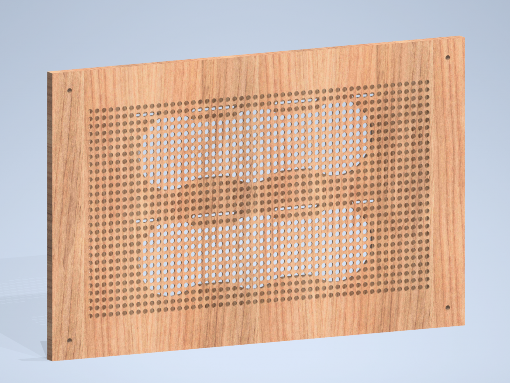
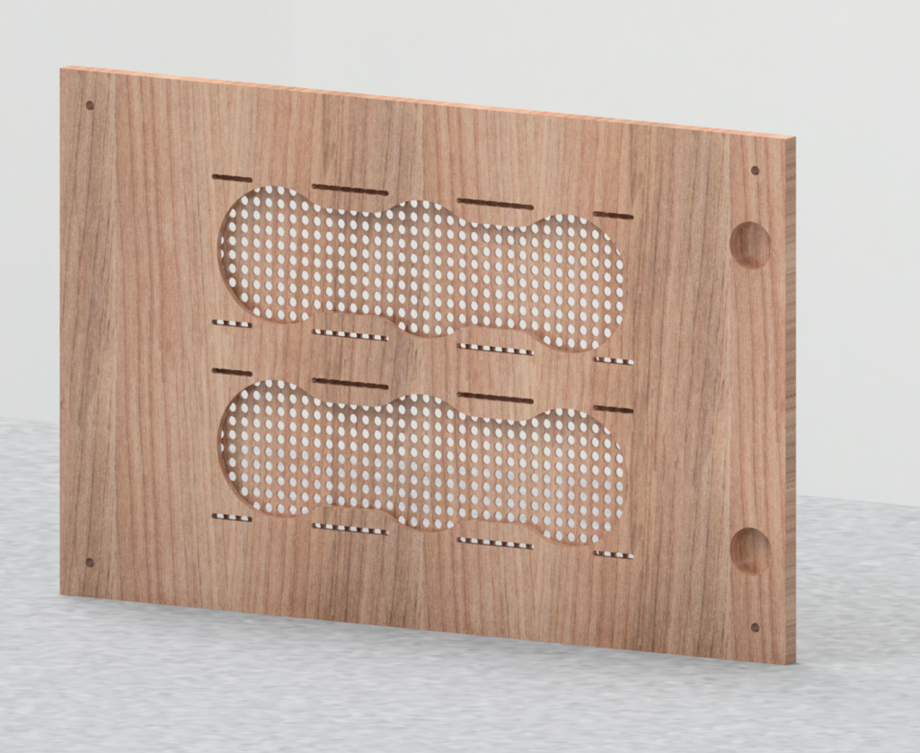
So one of the cool features that Inventor allows you to do is to test-fit your parts into assemblies before you get the chance to well, piece them together for realsies.
So, I did just that with the Besta PC Components I have so far just to showcase how awesome this door is going to look once done… Man, is it ever nice.
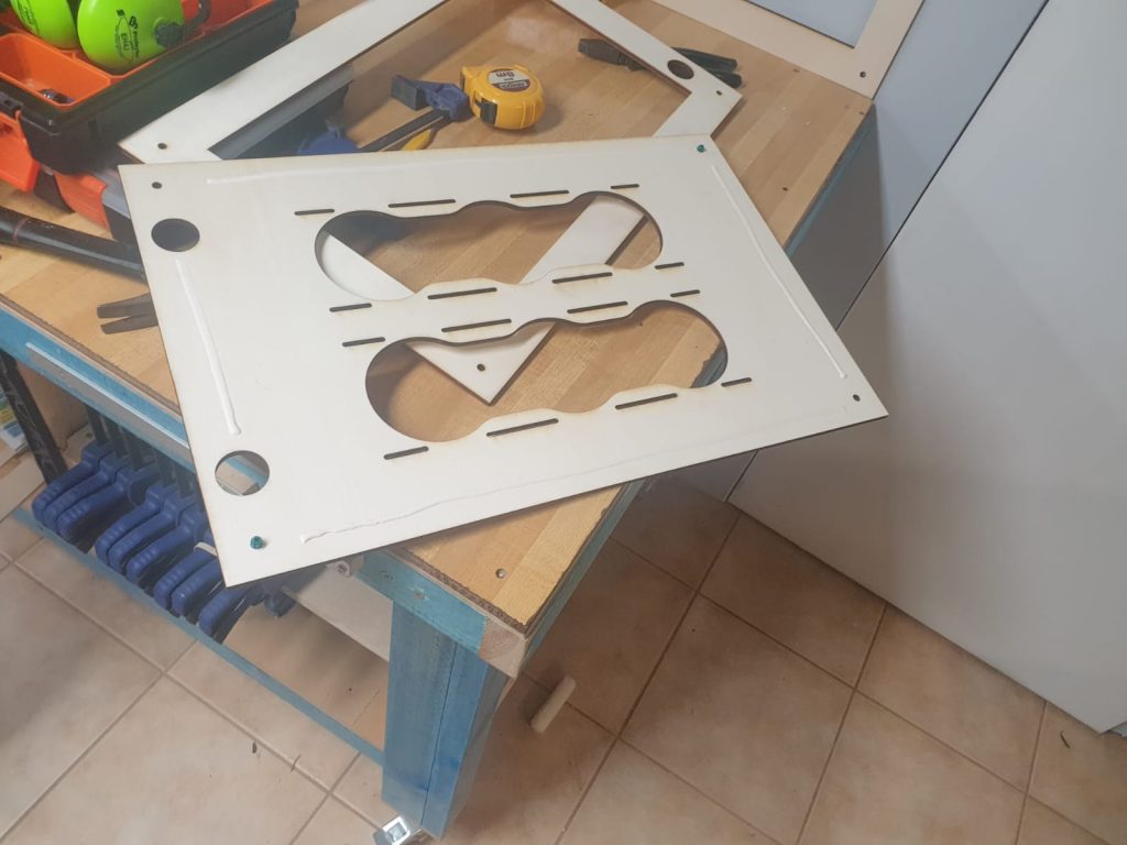
So now that we know they fit together nicely, it’s time for a shoutout. I met Nick from a little company based in Morley called PCI Laser Cutting, who took the time to cut these pieces out from plywood for us. A quick trip to Mum’s house, and we’re off to the races when it comes to assembly!
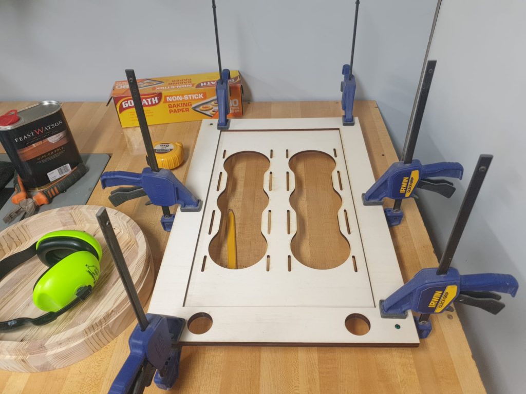
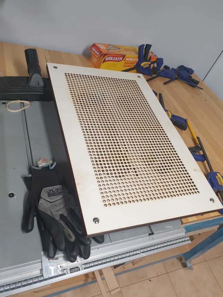
The layers were held together with Irwin Vise Grip clamps, and centred using some good ol’ green wall plugs. Gorilla Glue is used to hold the layers together. We then inserted 6x18mm nut inserts into the four corner holes to secure the door panels together. There’s a slight amount of splitting in the wood that happens when this occurs, but I worked out that you need to use a screwdriver instead of the ratchet that I was originally using. Turns out you need to apply a little pressure to the nutserts to get the threads to bite. Putting clamps on the corners also helped to stop any lifting of the corner layers.
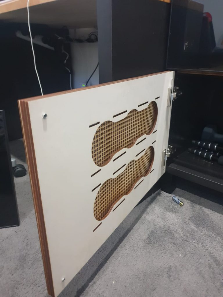
So… How does she look when it’s installed? Well this is only a Revision 1 prototype, and I’ve already identified a key flaw…
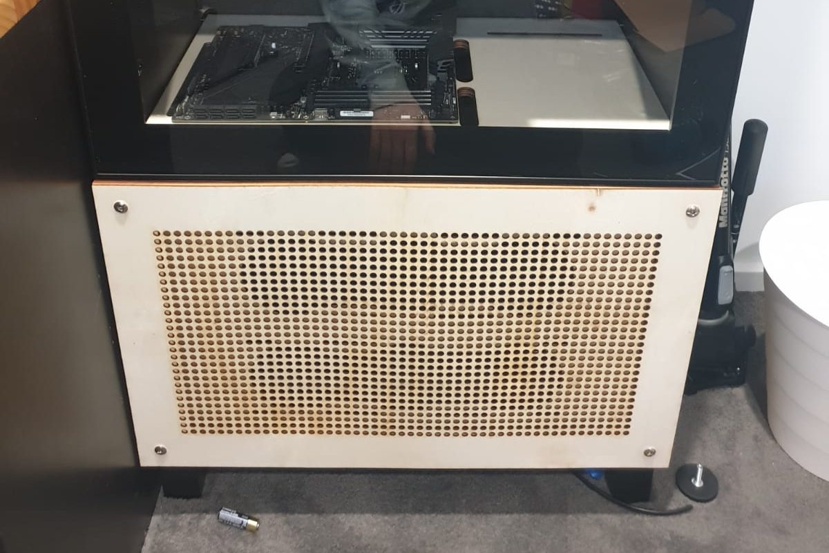
Don’t panic! It’s just the front panel. The frame itself is nice and sturdy, it’s just that the front face piece isn’t as sturdy, since it’s literally only three layers of veneered wood stacked together. As such it does bow a little in the center. The solution to this is to make this piece thicker and make the midframes thinner. The feasibility of this will be assessed when we finally get around to bolting Radiators to this. The Revision 2 version may even come with a steel backplate thanks to Nick providing me with a supplier who can do short laser cut steel runs. As for getting this particular one going? I might get another face cut with an acrylic front as opposed to the wood front.
All in all though, I’m incredibly happy with how the cutting turned out. The poplar looks great and as it’s a softer wood it cuts with minimal burning.
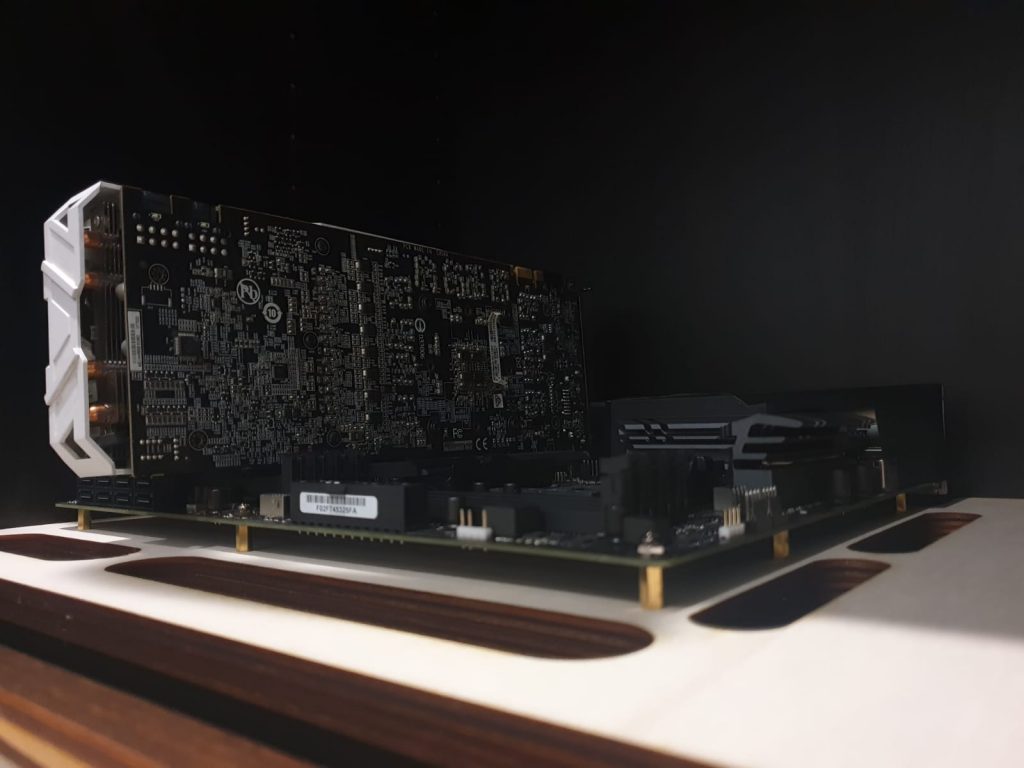
As for testing the mounting of the motherboard, I used a dead X570 board that has a dead memory slot and a dead BIOS to check the clearance of the posts for the shelf. As you can see, it fits in absolutely perfectly with M3 standoffs. These are actually bolts from a Tamiya DN01 kit (off the top of my head they’re M3x15mm) threaded into 10mm M3 standoffs sourced off an eBay seller. Then additional M3 screws are bolted through the motherboard to the standoffs to secure it in place.
So, what’s next is to replace the existing wooden face plate with an acrylic one, and to then set about printing and installing the PCI and PSU support brackets.
Stay tuned!